
Framework overview: why a structured approach matters
Adopting a repeatable framework reduces surprises when you install or expand high‑voltage 10 kWh battery containers for distributed power needs. This piece lays out a step‑by‑step framework that treats the system as engineering and operations work: site preparation, electrical integration, controls, testing, and handover. The approach is intentionally vendor‑neutral but practical — you’ll see where specification choices affect toolings, commissioning time, and lifecycle costs. If you’re evaluating a turnkey solar battery storage option or hybrid solution, this framework helps you ask the right questions up front.

1 — Define functional scope and constraints
Start by specifying the objective: peak‑shaving, backup power, frequency response, or pure resilience for a microgrid. Capture requirements in measurable terms — required kilowatt (kW) output, 10 kWh usable capacity per container, expected cycles/day, ambient temperature range, and expected lifetime. Include electrical constraints: whether the installation will be DC‑coupled or AC‑coupled, and whether the site has an existing inverter or needs a new power conversion system (PCS). The clearer the scope, the fewer surprises during procurement and commissioning.
2 — Site survey and civil preparation
Perform a thorough site survey that covers access, crane or forklift needs, foundation or pad loads, drainage, and proximity to the service transformer. High‑voltage containers require secure earthing, adequate clearance for ventilation, and a fire‑safe perimeter. Coordinate with local authorities for permits early — outages for grid‑tie work can be tightly scheduled. When adding modules later, ensure the pad and cable routes support expansion without extensive rework.
3 — Electrical architecture and integration
Design the single‑line electrical diagram before ordering equipment. Specify the BMS communication protocol, isolation transformer needs, busbar layout, and protection coordination. Decide how containers will interface with site controls: direct dispatch from a site energy management system, or local autonomous control via BMS. Include inverter and transformer ratings with short‑circuit and fault current analyses. Properly sized protection (breaker, fuse, relays) prevents nuisance trips and ensures safe islanding and reclosing sequences.
4 — Controls, monitoring and commissioning
Commissioning verifies function under real conditions: battery state of charge (SOC) assessments, charge/discharge setpoints, and telemetry to the supervisory system. Test BMS alarms, inverter fault handling, and communication redundancy. Perform a staged commissioning plan: factory acceptance tests, site dry‑commissioning, and full load commissioning with defined acceptance criteria. Document test results and include firmware versions for traceability. — A well‑run handover makes operations predictable.
5 — Safety, compliance and operations
Comply with local electrical codes and industry safety standards for high‑voltage battery systems. Implement locked access, arc‑flash boundaries, and an operational SOP for emergency shutdown. Train operations staff on BMS alerts, manual isolation, and safe work‑clearance procedures. Consider routine thermal imaging and SOC trending to catch degradation early. For deployments intended to support a microgrid energy storage application, ensure islanding protocols and black start sequencing are validated during commissioning.
Common mistakes and how to avoid them
Teams commonly underestimate thermal management, mismatch cell chemistry assumptions, or skip first‑article tests with actual site equipment. Tooling and connector lead times are often overlooked — procurement can be the bottleneck. Neglecting to test BMS‑to‑SCADA integration until late in the project invites schedule slip. Mitigation: require FATs, reserve contingency for spare parts, and specify acceptance test cases in the contract.
Comparative considerations when augmenting vs replacing
Augmenting an existing bank saves capital but can complicate controls and SOC management; replacing simplifies control architecture but increases up‑front costs. If the existing system uses a different BMS vendor or an older inverter platform, weigh the integration effort. Consider modular containers with standardised connectors and pre‑tested communication stacks to reduce field integration time. Lifecycle cost modelling usually favours standardisation when you expect future scaling.
Real‑world anchor: resilience lessons
The operational value of well‑installed storage is plain in events such as the February 2021 Texas winter outages: communities with local storage and clear islanding schemes restored critical services faster. That kind of resilience comes from planning — the right electrical architecture, tested controls, and rehearsed operational procedures — not from last‑minute improvisation.
Advisory close: three golden rules for evaluation
1) Evaluate on measurable metrics: required kW/kWh, round‑trip efficiency, and documented MTBF for power electronics. 2) Insist on testable integration: FAT reports, BMS‑to‑SCADA test scripts, and SOC verification with your actual loads. 3) Plan for scale: choose container and communication standards that allow hot‑addition without major rework.
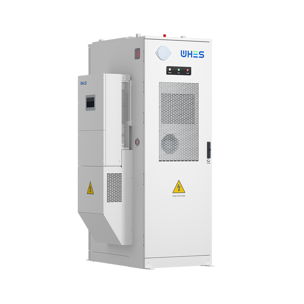
These rules make procurement and operations align — and they point you toward suppliers who move beyond marketing into measurable delivery. WHES provides integrated systems that map directly to these evaluation metrics, making the technical and commercial transition smoother — practical, dependable. —